Steel Rollers
Suitable for all applications and environments, Lorbrand manufactures one of the largest selections of steel conveyor rollers used extensively in overland applications around the world.
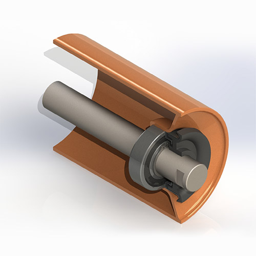
Incredibly robust, each roller consists of thick metal pressings which are MIG welded into conveyor-grade Electric Resistance Welded (ERW) tube, resulting in an extremely strong construction with low TIR (total indicator runout).
Key Aspects
- Diameters – 89—219mm
- Roll Lengths – 150—3000mm face length
- TIR – Typically less than 0.5mm at roll ends
- Bearing Sizes – Standard range 6204 to 6312
- Noise – typically less then 75 dBA
- Centrifugal labyrinth sealing arrangement
- Material Specifications – SANS 657 III conveyor-grade steel tube
Steel Rollers Range
Our product range is not limited to these sizes. Please contact Lorbrand for more information on our full product range.
| SERIES | DIAMETER (mm) | SHELL WALL (mm) | NOMINAL SHAFT DIAMETER (mm) | BEARING PART NO. | MIN BEARING DYNAMIC LOAD RATING (N) |
|---|---|---|---|---|---|
| 20 | 89 | 3 | 20 | 6204 – 2RS | 12 700 |
| 102 | 3.5 | ||||
| 114 | 3.5 | ||||
| 127 | 3.8 | ||||
| 25 | 102 | 3.5 | 25 | 6205 – 2RS | 14 000 |
| 114 | 3.5 | ||||
| 127 | 3.8 | ||||
| 133 | 4 | ||||
| 139 | 4 | ||||
| 152 | 4 | ||||
| 159 | 4 | ||||
| 27 | 127 | 3.8 | 25 | 6305 – 2RS | 22 500 |
| 133 | 4 | ||||
| 139 | 4 | ||||
| 152 | 4 | ||||
| 159 | 4 | ||||
| 32 | 127 | 3.8 | 30 | 6306 – 2RS | 28 100 |
| 133 | 4 | ||||
| 139 | 4 | ||||
| 152 | 4 | ||||
| 159 | 4 | ||||
| 178 | 6 | ||||
| 35 | 152 | 6 | 35 | 6307 – 2RS | 33 200 |
| 159 | 6 | ||||
| 178 | 6 | ||||
| 40 | 152 | 6 | 40 | 6308-2RS | 41 000 |
| 159 | 6 | ||||
| 178 | 6 | ||||
| 193 | 6 | ||||
| 219 | 6 | ||||
| 45 | 152 | 6 | 45 | 6309 – 2RS | 52 700 |
| 159 | 6 | ||||
| 178 | 6 | ||||
| 193 | 6 | ||||
| 50 | 178 | 6 | 50 | 6310 – 2RS | 61 800 |
| 193 | 6 | ||||
| 60 | 178 | 6 | 60 | 6312 – 2RS | 81 900 |
| 219 | 6 |
Shell wall thickness for CEMA idlers and rollers sized to meet CEMA guidelines for rotating mass and WK2 values. Thinner wall thicknesses available on request.
| SERIES | DIAMETER (mm) | SHELL WALL (mm) | NOMINAL SHAFT DIAMETER (mm) | BEARING PART NO. | MIN BEARING DYNAMIC LOAD RATING (N) |
|---|---|---|---|---|---|
| 20 | 89 | 3 | 20 | 6204 – 2RS | 12 700 |
| 102 | 3.5 | ||||
| 114 | 3.5 | ||||
| 127 | 3.8 | ||||
| 25 | 102 | 3.5 | 25 | 6205 – 2RS | 14 000 |
| 114 | 3.5 | ||||
| 127 | 3.8 | ||||
| 133 | 4 | ||||
| 139 | 4 | ||||
| 152 | 4 | ||||
| 159 | 4 | ||||
| 27 | 127 | 3.8 | 25 | 6305 – 2RS | 22 500 |
| 133 | 4 | ||||
| 139 | 4 | ||||
| 152 | 4 | ||||
| 159 | 4 | ||||
| 32 | 127 | 3.8 | 30 | 6306 – 2RS | 28 100 |
| 133 | 4 | ||||
| 139 | 4 | ||||
| 152 | 4 | ||||
| 159 | 4 | ||||
| 178 | 6 | ||||
| 35 | 152 | 6 | 35 | 6307 – 2RS | 33 200 |
| 159 | 6 | ||||
| 178 | 6 | ||||
| 40 | 152 | 6 | 40 | 6308 – 2RS | 41 000 |
| 159 | 6 | ||||
| 178 | 6 | ||||
| 193 | 6 | ||||
| 219 | 6 | ||||
| 45 | 178 | 6 | 45 | 6309 – 2RS | 52 700 |
| 193 | 6 |
Shell wall thickness for CEMA idlers and rollers sized to meet CEMA guidelines for rotating mass and WK2 values. Thinner wall thicknesses available on request.
| SERIES | DIAMETER (mm) | SHELL WALL (mm) | NOMINAL SHAFT DIAMETER (mm) | BEARING PART NO. | MIN BEARING DYNAMIC LOAD RATING (N) |
|---|---|---|---|---|---|
| 20 | 89 | 3 | 20 | 6204 – 2RS | 12 700 |
| 102 | 3.5 | ||||
| 114 | 3.5 | ||||
| 127 | 3.8 | ||||
| 25 | 102 | 3.5 | 25 | 6205 – 2RS | 14 000 |
| 114 | 3.5 | ||||
| 127 | 3.8 | ||||
| 133 | 4 | ||||
| 139 | 4 | ||||
| 152 | 4 | ||||
| 159 | 4 | ||||
| 27 | 127 | 3.8 | 25 | 6305 – 2RS | 22 500 |
| 133 | 4 | ||||
| 139 | 4 | ||||
| 152 | 4 | ||||
| 159 | 4 | ||||
| 32 | 152 | 4 | 30 | 6306 – 2RS | 28 100 |
| 159 | 4 | ||||
| 178 | 6 | ||||
| 35 | 152 | 6 | 35 | 6307 – 2RS | 33 200 |
| 159 | 6 | ||||
| 178 | 6 | ||||
| 40 | 152 | 6 | 40 | 6308 – 2RS | 41 000 |
| 159 | 6 | ||||
| 178 | 6 | ||||
| 193 | 6 | ||||
| 219 | 6 | ||||
| 45 | 178 | 6 | 45 | 6309 – 2RS | 52 700 |
| 193 | 6 |
Shell wall thickness for CEMA idlers and rollers sized to meet CEMA guidelines for rotating mass and WK2 values. Thinner wall thicknesses available on request.
| SERIES | DIAMETER (mm) | SHELL WALL (mm) | NOMINAL SHAFT DIAMETER (mm) | BEARING PART NO. | MIN BEARING DYNAMIC LOAD RATING (N) |
|---|---|---|---|---|---|
| SABS 25 | 127 | 3.8 | 25 | 6205 – 2RS | 14 000 |
| 152 | 4 | ||||
| SABS 30 | 152 | 4 | 30 | 6306 – 2RS | 28 100 |
| 178 | 6 | ||||
| SABS 35 | 152 | 6 | 35 | 6307 – 2RS | 33 200 |
| 178 | 6 | ||||
| SABS 40 | 152 | 6 | 40 | 6308 – 2RS | 41 000 |
| 178 | 6 |
| SERIES | DIAMETER (mm) | SHELL WALL (mm) | NOMINAL SHAFT DIAMETER (mm) | BEARING PART NO. | MIN BEARING DYNAMIC LOAD RATING (N) |
|---|---|---|---|---|---|
| SABS 25 | 127 | 3.8 | 25 | 6205 – 2RS | 14 000 |
| 152 | 4 | ||||
| SABS 30 | 152 | 4 | 30 | 6306 – 2RS | 28 100 |
| SERIES | DIAMETER (mm) | SHELL WALL (mm) | NOMINAL SHAFT DIAMETER (mm) | BEARING PART NO. | MIN BEARING DYNAMIC LOAD RATING (N) |
|---|---|---|---|---|---|
| SABS 25 | 127 | 3.8 | 25 | 6205 – 2RS | 14 000 |
| 152 | 4 | ||||
| SABS 30 | 152 | 4 | 30 | 6306 – 2RS | 28 100 |
Deep groove double sealed or shielded bearings, of tolerance class C3 and C4, are used. This allows for a larger amount of angular misalignment at the bearing when compared with other bearing designs and classes.
Steel Tube
Only high-quality tube specially manufactured for conveyor idlers is used and conforms to SABS 657/3 (1980). Shell ends are machined to prevent belt wear.
Steel Shaft
Manufactured from steel which complies with the requirements for grade 070 M20 of BS 970-1. Shaft diameter tolerance adheres to bearing manufacturer standards and ensures a js6 fit. Shaft end slots are machined to customer standards.
Hollow Shaft
Stepped lightweight hollow steel shafts, equivalent in strength and rigidity to solid shafts, are available on request.
Bearing Housing
Manufactured from deep drawing steel to EN 10111(DD14). Housings are pressed and MIG welded to the inside of the tube.
Corrosion Protection
An external coat of self-etching primer is applied unless otherwise specified.
Circular Movement Tolerance (TIR)
TIR does not exceed 0,5mm measured at a distance of 25mm from the roller end face. Actual TIR values are less and can be verified by referencing historical data.
| ROLLER FACE LENGTH (MM) | TIR | |
|---|---|---|
| D<=127 | D>127 | |
| Up to 536 | 0.5 | 0.6 |
| 586 to 965 | 0.7 | 0.9 |
| 994 to 1 450 | 1.3 | 1.6 |
| 1 602 to 2 518 | 1.9 | 2.3 |
Lorbrand conveyor Idlers have frictionless seals. Idler drag is due to bearings only and is therefore easy to predict. Drag is dependent on factors such as loading, rpm, bearing type, characteristics and temperature.
Please consult Lorbrand for friction values.
Lorbrand is able to test rollers according to CEMA (Edition 6, Appendix F) “Kis” test procedures and actual friction values under various load and ambient temperature conditions. Tests can be performed on bearings supplied for a particular project. Typical friction values for 3 roll carry idlers, at rated load running at 500rpm, are listed below:
| BW | BW | 3 Roll Carry Idler Running Friction (N) | |||||
|---|---|---|---|---|---|---|---|
| in | mm | CEMA B 6204 | CEMA C 6205 | ||||
| rated load | 3 rolls | 3 rolls | rated load | 3 rolls | 3 rolls | ||
| kg | 102 DIA | 127 DIA | kg | 102 DIA | 127 DIA | ||
| 400 | |||||||
| 18 | 450 | 186 | 2.3 | 1.9 | 409 | 3.5 | 3.0 |
| 20 | 500 | 186 | 2.3 | 1.9 | 409 | 3.5 | 3.0 |
| 24 | 600 | 186 | 2.3 | 1.9 | 409 | 3.5 | 3.0 |
| 30 | 750 | 186 | 2.3 | 1.9 | 409 | 3.5 | 3.0 |
| 36 | 900 | 186 | 2.3 | 1.9 | 380 | 3.4 | 2.8 |
| 1000 | 175 | 2.3 | 1.8 | 370 | 3.3 | 2.8 | |
| 42 | 1050 | 165 | 2.2 | 1.8 | 360 | 3.2 | 2.7 |
| 48 | 1200 | 160 | 2.2 | 1.8 | 338 | 3.1 | 2.6 |
| 54 | 1350 | 317 | 3.0 | 2.5 | |||
| 1400 | 310 | 2.9 | 2.4 | ||||
| 60 | 1500 | 295 | 2.8 | 2.4 | |||
| BW | BW | 3 Roll Carry Idler Running Friction (N) | |||||
|---|---|---|---|---|---|---|---|
| in | mm | SERIES 27 6305 | SERIES 30 6206 | ||||
| rated load | 3 rolls | 3 rolls | rated load | 3 rolls | 3 rolls | ||
| kg | 127 DIA | 152 DIA | kg | 127 DIA | 152 DIA | ||
| 400 | |||||||
| 18 | 450 | 409 | 3.8 | 3.2 | |||
| 20 | 500 | 409 | 3.8 | 3.2 | |||
| 24 | 600 | 409 | 3.8 | 3.2 | 464 | 4.7 | 4.0 |
| 30 | 750 | 409 | 3.8 | 3.2 | 464 | 4.7 | 4.0 |
| 36 | 900 | 380 | 3.7 | 3.1 | 464 | 4.7 | 4.0 |
| 1000 | 370 | 3.6 | 3.0 | 464 | 4.7 | 4.0 | |
| 42 | 1050 | 360 | 3.5 | 3.0 | 464 | 4.7 | 4.0 |
| 48 | 1200 | 338 | 3.4 | 2.9 | 464 | 4.7 | 4.0 |
| 54 | 1350 | 317 | 3.3 | 2.8 | 391 | 4.2 | 3.5 |
| 1400 | 310 | 3.2 | 2.7 | 385 | 4.2 | 3.5 | |
| 60 | 1500 | 295 | 3.2 | 2.7 | 375 | 4.1 | 3.4 |
| 1600 | 365 | 4.0 | 3.4 | ||||
| 72 | 1800 | 343 | 3.9 | 3.2 | |||
| BW | BW | 3 Roll Carry Idler Running Friction (N) | |||||
|---|---|---|---|---|---|---|---|
| in | mm | CEMA D 6306 | SERIES 35 6307 | ||||
| rated load | 3 rolls | 3 rolls | rated load | 3 rolls | 3 rolls | ||
| kg | 152 DIA | 178 DIA | kg | 152 DIA | 178 DIA | ||
| 24 | 600 | 545 | 4.7 | 4.0 | |||
| 30 | 750 | 545 | 4.7 | 4.0 | |||
| 36 | 900 | 545 | 4.7 | 4.0 | 818 | 7.4 | 6.3 |
| 1000 | 545 | 4.7 | 4.0 | 818 | 7.4 | 6.3 | |
| 42 | 1050 | 545 | 4.7 | 4.0 | 818 | 7.4 | 6.3 |
| 48 | 1200 | 545 | 4.7 | 4.0 | 818 | 7.4 | 6.3 |
| 54 | 1350 | 507 | 4.5 | 3.9 | 818 | 7.4 | 6.3 |
| 1400 | 500 | 4.5 | 3.8 | 818 | 7.4 | 6.3 | |
| 60 | 1500 | 486 | 4.4 | 3.7 | 818 | 7.4 | 6.3 |
| 1600 | 472 | 4.3 | 3.7 | 818 | 7.4 | 6.3 | |
| 72 | 1800 | 444 | 4.1 | 3.5 | 818 | 7.4 | 6.3 |
| 2000 | 780 | 7.1 | 6.1 | ||||
| 84 | 2100 | 761 | 7.0 | 6.0 | |||
| 96 | 2400 | 740 | 6.8 | 5.8 | |||
| BW | BW | 3 Roll Carry Idler Running Friction (N) | |||||
|---|---|---|---|---|---|---|---|
| in | mm | CEMA E 6308 | SERIES 45 6309 | ||||
| rated load | 3 rolls | 3 rolls | rated load | 3 rolls | 3 rolls | ||
| kg | 152 DIA | 178 DIA | kg | 152 DIA | 178 DIA | ||
| 36 | 900 | 818 | 8.6 | 7.3 | |||
| 1000 | 818 | 8.6 | 7.3 | ||||
| 42 | 1050 | 818 | 8.6 | 7.3 | |||
| 48 | 1200 | 818 | 8.6 | 7.3 | |||
| 54 | 1350 | 818 | 8.6 | 7.3 | |||
| 1400 | 818 | 8.6 | 7.3 | ||||
| 60 | 1500 | 818 | 8.6 | 7.3 | 1250 | 13.6 | 11.6 |
| 1600 | 818 | 8.6 | 7.3 | 1250 | 13.6 | 11.6 | |
| 72 | 1800 | 818 | 8.6 | 7.3 | 1250 | 13.6 | 11.6 |
| 2000 | 780 | 8.3 | 7.1 | 1250 | 13.6 | 11.6 | |
| 84 | 2100 | 761 | 8.2 | 7.0 | 1250 | 13.6 | 11.6 |
| 96 | 2400 | 740 | 8.0 | 6.8 | 1150 | 12.7 | 10.9 |
| BW | BW | 3 Roll Carry Idler Running Friction (N) | ||||
|---|---|---|---|---|---|---|
| in | mm | CEMA F 6310 | SERIES 60 6312 | |||
| rated load | 3 rolls | 3 rolls | rated load | 3 rolls | ||
| kg | 178 DIA | 219 DIA | kg | 219 DIA | ||
| 60 | 1500 | 1364 | 14.0 | 11.4 | ||
| 1600 | 1364 | 14.0 | 11.4 | |||
| 72 | 1800 | 1364 | 14.0 | 11.4 | 1600 | 16.1 |
| 2000 | 1364 | 14.0 | 11.4 | 1600 | 16.1 | |
| 84 | 2100 | 1364 | 14.0 | 11.4 | 1600 | 16.1 |
| 96 | 2400 | 1273 | 13.3 | 10.8 | 1600 | 16.1 |
| 108 | 2500 | 1600 | 16.1 | |||
| 2600 | 1600 | 16.1 | ||||
| 2800 | 1600 | 16.1 | ||||
| 3000 | 1600 | 16.1 | ||||
Primary Seal
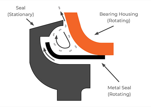
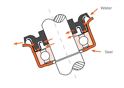
Any dirt that enters the primary seal is collected and then allowed to escape by being flung radially outward through centrifugal force.
Secondary Seal
Most secondary seals on the market utilise a labyrinth design which prevents dirt from escaping the sealing area—with centrifugal force actually keeping dirt in—before working its way back to the bearing.
Lorbrand’s secondary seals avoid this problem because all sealing surfaces are free from contact, they do not require packing with grease and the seal arrangement allows water to drain freely when the roller is stationary. The result: dirt is unrestricted when being propelled outwards by centrifugal force.
Bearing Seal
As the final barrier against dirt ingress, especially rust particles that form due to condensation inside the shell tube, each Lorbrand bearing features seals on both sides and is lubricated for life.


